Friday, December 27, 2013

Sheathing Part II

When the weather (and holiday schedule) has allowed them to work, the framers have been finishing the wall sheathing and applying the roof sheathing. The new house next door was all decked out for Christmas in red and green!


(Red) Advantex roof sheathing over the trusses on the second floor (because they are 2'-0" on center and need a material that is rated to span that) and (green) Zip sheathing on the low, stick framed roof over the kitchen and dining room (where the framing is 16" on center).

Both of these sheathings are a bit more high-tech than plain old plywood. (though not as high tech as the Zip-R wall sheathing that has integrated rigid insulation as well) The red or green color is actually an integral water management membrane, so a separate one is not needed. Dan, the contractor, likes to use these products because of the time savings. The guys install it once and don't have to go back over the entire area again to apply roofing paper or house wrap.


Snow, Roofs & Trusses

It's been snowing lately...I guess when one sighs about rain in December on the Internet, the universe listens! It's very pretty, and not really enough to disrupt life - other than to keep the framers away! I was told that they really dislike having to shovel the inside of a house. (fair enough!)


Last week the roof trusses got delivered. Note the special trailer with no bottom in the middle such that the peak of the roof (pointing down toward the road) is so close - almost touching! - the ground.

After the trusses were unloaded from the truck, the driver tried to leave, but he was stuck for a while while the framers tried to dig him out. (who knew how much shoveling a framer has to do?!)
cut sheet from the truss manufacturer

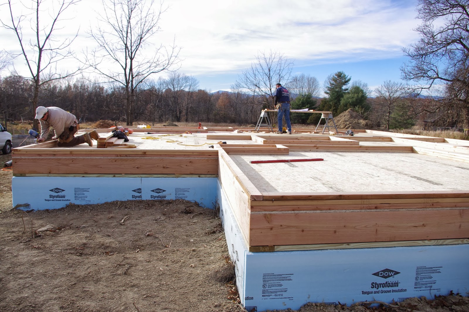
Trusses are interesting. They are factory built using lumber and fasteners under an engineers guidance (rather than the alternative - "stick built"- which, like the walls and floor are assembled on site from individual pieces. The main advantage of trusses (to the architect) is that they can span much farther than stick framing. The interior partitions are not load bearing at all and so can be placed (or removed) anywhere. To the builder, I'd guess the advantage is how quickly the roof can be put on.

This is an "attic truss", which means it is designed to have a floor for storage right down the middle (highest area) of the space.

Once the trusses were on site, the framers worked to apply the rake overhang. The rake is the edge of the roof by the triangle- or gable. (as opposed to the eave overhang - which is created by the rafter tail). They build this like a little ladder and attach it to the gable end truss. As as aside, overhangs are useful. They create shadows and shade and they protect the walls from weather, directing water away from the wall. Plus, they can really add an architectural statement, if proportioned and detailed correctly.


Crane lifting roof trusses into place
Trusses are in place and diagonally braced until sheathed. You can see the rake overhang silhouetted against the sky
Later in the week, a crane came to the site. The crane and a crew of a few guys worked to precisely place and secure the main roof trusses as per the 2'-0" on center layout. The framers also started applying the fascia, which is the board along the bottom edge of the roof truss tail. (where the gutter will be installed). Now the roof is ready for sheathing! And that means no more shoveling inside the house. Yay!

Thursday, December 12, 2013

Floor Plans

So it occurs to me I have shown the site plan way back in my first post and the front elevation in my "Context" post... but I haven't shared the floor plans yet!
Here are the drawings showing the layout:

Thursday, December 5, 2013

Sheathing & CI

When it's not raining too much for them to work, (Sigh! Rain in December?!) the sheathing is going onto the outside of the exterior wall framing.


In most of today's building, sheathing is 4'x8' sheets, installed horizontally, to the outside edge of the wall studs. If structural, sheathing provides lateral (forces from the side, like wind) support to the walls. Once the sheathing is installed, those temporary diagonal braces we saw placed around the structure can be safely removed.

Typical structural sheathing might be plywood or OSB (oriented strand board). Non-structural sheathing could be rigid foam board. If non-structural sheathing is used alone, lateral bracing needs to be accomplished with metal strapping or let-in wood braces.

The product being used on the new house next door is a fabricated sheet that integrates the structural sheathing along with rigid foam and a water management barrier. Instead of three different materials, this product - called Zip R - is all of them on one board. Kind of neat - and a labor saver for the workers.

The continuous 1" of rigid insulation that is part of the Zip R provides R-5 insulation value to the wall. But R value is not the whole story... Building scientists have studies thousands of buildings and learned that just having a high R value is not the silver bullet we all once thought it was. Wall studs are responsible for thermal bridging (a connection from out to in and vice-versa) creating a conduit for moisture and heat to travel through the wall. (that's a bad thing) Continuous insulation stops thermal bridging. So do insulated headers. CI also puts the insulation on the outside of the wall, and with taped seams can be a fairly effective air barrier as well. That little ol' R-5 does a lot for the wall as a system. That's why I could then frame the walls from 2x4s (instead of 2x6s) because I didn't need such a thick cavity space for a higher R value in my wall cavity.

Wednesday, December 4, 2013

Advanced Framing

I wanted to try out advanced framing techniques with this house. Here is what that means and what I've learned so far...

Advanced framing means framing smart with the goal being to minimize over-use of wood and redundancy. Some tried and true ways to frame a wall or floor or window opening have been analyzed because some of them are putting extra wood where it really isn't needed. Advanced framing came into being because often walls are insulated within the cavity - the spaces between the wood - and if we want to make a wall better insulated, we want there to be less wood and more space for insulation. Also, wood is not such a cheap and accessible resource as it once was.


solid headers where required to transfer loads from above and open framing above openings in non-load-bearing walls


There are some basic wood saving techniques that are easy to implement and are worth thinking about. These include open rather than solid corners, omitting headers in non-load-bearing walls and even omitting jack studs in favor of header clips. On a small building, stacking framing and using single top plates is intriguing. (I found it incompatible for this design because I wanted to use roof trusses @ 24" o.c. and 2x4 wall studs, which couldn't be 24" o.c. in two story construction by NYS code.)

Some of the suggestions to minimize framing around openings seem to only be applicable if the interior and exterior casing are very minimal. For this project, we had to have double studs each side of a window for the trim to have something to nail into.

So, it has been an interesting experiment. And I see the short-comings of advanced framing. Like other engineering ideas, they leave little room for aesthetics. When windows are centered or placed deliberately (like on the front gable elevation) it is quite difficult to plan for non-redundant studs. When open spaces require rotated floor joists, headers are now required on both the gable and eave walls. And, like I mentioned, if one wants nice wood trim (inside) and casing around the windows (outside), then wood of more than one stud width is required for nailers.

Ah, well... Next we will be building a simple, one floor, rectangular open room wood shop building for my husband. The simplicity of that structure allows for more advanced framing techniques to be implemented. Like everything, it's a balancing act...


Moving on up...

The second floor walls are built now. Even without the roof, the view of my (former) closest neighbor is now obscured when I look out my window because of the height of the new house next door.
now you see J&L's house...
second floor walls under construction


Some folks I talk to are surprised that a house designed for senior citizens has a second floor. There are a few reasons. First, the village pattern book required it. Traditionally, village buildings are not ranches, so in order to "fit in", new construction should be more than one floor.

Second, once my in-laws understood that to build next door to their son they needed a second floor to meet the code, they stopped looking at ranch plan books and started realizing something. Their peers who had down-sized to one-level living were no longer physically able to easily climb stairs. It's that "use it or lose it" principle. Having stairs started to seem like a good way to get some exercise and stay fit while they age.

A quick internet search shows that this is not a new idea. Organizations and communities exist which promote "healthy design", including encouraging stair climbing by having open, visible, well-designed stairs.We are talking mostly about commercial buildings, where one typically is directed to the elevator... or if you search it out, you have to option of opening a door to take a bleak looking set of concrete steps- the code-mandated enclosed fire-rated egress stair.

I've been at the hospital the last few days visiting a family member. The corridors and signage direct visitors to the elevators, but yesterday I sought out the stair instead. As expected, it was grim (bare and windowless with utilitarian signage announcing "No Roof Access" - you know what I mean). It would be nice if future commercial building designs could encourage the occupants to exercise by offering nice stairways someday. For now, I will take the stairs despite their unattractiveness. What I do see more and more is another smiling face climbing with me.


Monday, November 25, 2013

Porch Footings

Digging the hole for front porch footings
 Today the excavator came back for the day. He backfilled around the garage slab and dug holes for the front and back porch piers.

You can see the precast piers standing in the background of the first photo. Then you can barely see the tops of them poking out of the ground in the second photo after they were placed precisely (within 1" each direction) as per the plan to support the wood framing that will go above it.


Three front porch footings installed
A porch (or a whole building, really) can have a floor system than is supported by piers and is over open air, rather than a full foundation wall enclosing a basement or crawlspace. This is much less expensive, and often done under exterior spaces, like decks.

On previous projects I've seen cardboard sono-tubes placed into the hole, and then filled with concrete and re-bar. ("poured in place", like the rest of the concrete work you've seen on this project). This was different, because the G.C. elected to use precast pier footings. They came delivered to the site yesterday and got installed and back-filled today. Quick and done!

Digging for the back porch pier footing
Placing the pier. Don't put it on Scott's foot!


Tuesday, November 19, 2013

Structural Primer

Today you will get a structural lesson. Does that sound boring and too math heavy? Well, it's not!

We could set this post to the tune of that old song: "The Knee Bone's Connected to the...Thigh Bone!"  Why? Because that's what it's like. Trusses or rafters bear on walls or beams; walls bear onto floor joists or joist beams; floor joists rest on girders; beams span openings in walls and they are supported by posts at each end, posts are point loads that need land onto beams or girders; and eventually it all comes down to the concrete footers that are underground.

First some definitions:
  • A Girder is a built-up beam that supports the main floor joists. It is in the crawlspace.You can probably see one in your basement, if it's unfinished.
  • Joists are the repetitive members that make up a floor or ceiling system. They can be supported by beams or walls or a combination of both.
  • Rafters are the repetitive members that make up a roof system (along with a ridge board or beam and possibly collar ties)
  • Beams span an opening (like over a door or window) and joists rest on top of them.
  • Joist Beams are in the same plane as the joists, but are built-up of more than one unit to accept a load that will be there.
  • Flush Beams are not dropped under what they support (like the girder) but rather are flush - or even- with the joists it supports. Hardware like joist hangers are needed for this to work.
  • Posts can be a couple of studs put together to support each end of a beam or such
  • Columns are round (as opposed to square edged posts) but are also vertical point-load carrying members.
  • Bearing Walls are when all the wall studs as a unit provide continuous support
  • Trusses are factory made (usually), can span long distances for floors or roofs, and bear outside wall to outside wall (so interior partitions are just dividers, not structural)
  • Engineered Lumber is made from cut wood, sawdust and glue and is much stronger (really!) and can span farther than 
  • Dimensional Lumber, which is 2x4s, 2x6s, 2x8s, 2x10s & 2x12s comes in a few different species, each with it's own strength and span characteristics.
Well - this is getting long, but stay with me. Here are some photos to put it all together:
Main Girder supports mid-span of floor joists. In this case it is a built-up engineered beam (Three LVLs put together) The framers are cutting a column to the correct height
Girder rests in beam pockets in the concrete wall and onto steel columns that bear onto interior concrete footings. Floor joists will run perpendicular the the girder and across the top of it out toward each side wall

Floor joists span from the foundation wall (sill plate, actually) to the main girder. Here is also a cantilever, which means the joists extend beyond the support  of the foundation wall over open air

Header with posts each end (over opening on the right) Flush beam (on top of wall by John's hand) Second floor joists will attach into that flush beam and run perpendicular to it
Long LVL beam will carry roof, floor and wall loads from above so the space can be open (ie. not have a wall there) This beam has posts at each end and mid-span, buried within the stud walls
Second floor joists - some running east-west landing on a bearing wall, some running north-south where Scott is installing more; also see headers over windows, because regardless of floor joist direction, that exterior wall will be carrying the main roof's load

It's just like Lincoln Logs! Well, maybe not... Did this help any of you understand a bit of how a house is framed? Now you should be able to look around your own house and figure out which walls (non-load bearing) can be changed easily to have a wider opening or a larger window- and which walls or beams are keeping the floor from collapsing when you dance and jump around.

Monday, November 18, 2013

First Floor

Last week they did all the layout for all interior and exterior walls on the first floor. It looked like a full scale floor plan, with stacked sill plates as the lines denoting the walls arranged on the floor.
 
 Next they built the walls, putting vertical pieces (studs) between bottom plate and top plate and voila - it is looking more like a house than a dance floor! Now you can really walk around inside and see what the rooms feel like.(the diagonal boards you see are temporary bracing and will go away when the walls are given the lateral support that plywood provides)

 As the architect, I like to walk around in the new space and see if anything feels different than I envisioned it when I designed and drew it. It doesn't.

The general contractor verified that all the walls, headers and door/window openings are as they should be. He caught a few spots (a wall under the stairs that doesn't need to be there since it is an open riser stair, a header required where floor joists are to be rotated) that needed a small fix.

As for the framer, he is measuring and making sure the loads all align. This is tricky, to me - because he has to do it "backwards" and "blind". The reason I say that is that I design the loads from the top down, and visually ensure they align on my drawings. The framer of course, has to build from the bottom up, and each layer gets hidden (by the plywood sub-floor) covering the structure below that he needs to land on.

For my mother-in-law, this will be a chance to walk around in the spaces and get more of a feel for the house than I think she could from the floor plans and building sections.

Next up: second floor! (what else would come after first floor?!)

Wednesday, November 13, 2013

A Window into the Architect's Process

While the framers are busy building floors next door, I am reviewing the window schedule at my desk. This house has around 28 windows, and I had to review them and revise some of them.

The building code requires windows in habitable space. There are requirements for natural light and natural ventilation. There are requirements for emergency egress. There are requirements that the actual window unit installed meets certain energy standards. These requirements must be balanced with the aesthetics from both inside and outside and with the function and use of the spaces.

Excerpt from SECTION R303
LIGHT, VENTILATION AND HEATING
All habitable rooms shall be provided with aggregate glazing area of not less than 8% of the floor area of such rooms. Natural ventilation shall be through windows, doors, louvers, or other approved openings to the outside air. Such openings shall be provided with ready access or shall otherwise be readily controllable by the building occupants. The minimum area to the outdoors shall be 4% of the floor area being ventilated...

There are exceptions (like bathrooms) and special rules for adjoining rooms. It is not a coincidence that the area of light required is double the ventilation area required - think of a "double hung" style window (typical in the Northeast)It offers twice as much light as ventilation. We like light in our homes. Architects like to use a lot of windows. Designs today generally do not have a problem meeting these requirements.

Excerpt from SECTION R301
EMERGENCY ESCAPE AND RESCUE OPENINGS
Basements with habitable space and every sleeping room shall have at least one openable emergency escape and rescue opening... they shall have a sill height of not more than 44" above the floor.... minimum net clear opening of 5.7 square feet... minimum net clear opening height shall be 24"... minimum width shall be 20"... shall be operational from the inside of the room without the use of keys or tools...
The three bedrooms on the second floor of this house each need an egress window. This architectural style typically utilizes double hung windows, but with only one sash - bottom or top- opening, a double hung window has to be excessively large to meet the clear opening area requirements. (this large opening is to accommodate a fire-fighter, in full gear, climbing in to rescue you). Such a large window would look WAY out of proportion, especially on the second floor, so architects have a trick. I specified one casement window, the same size as the double hung windows in the bedroom and with a lite pattern to match. (so it has a horizontal band across the middle, to make it look like two sashes) A better proportioned casement can meet the egress dimension requirements, because the whole window swings open from the side.


Windows are so important in our buildings for views, light, air, and safety. I hope this post gave you a "glimpse" into some of the things an architect has to consider. We'll talk about the energy efficiency of windows in a future post.


The Letter of the Day is "F"

Frost on the Framing this morning! Today was very cold all day - honestly I cannot imagine working outside all day in temps like this- but Scott and John did it. And they Finished the First Floor!


If there was a sound of the day, it would be a loud BOOM. This was the sound that rang out periodically as the guys aligned the edge of each 4' x 8' sheet of 3/4" plywood (read: HEAVY!) against the previous sheet and let it fall into place.

Yesterday they had finished installing the floor joists and girders and steel columns in the crawlspace. We'll look more at how that all fits together in another post. The crawlspace is covered over now, with the only way inside through the opening in the back of the foundation. There will be a floor hatch, but they've decided to frame that later.

Sill plates are next, and marking out the interior wall locations. If the plates around the perimeter look "skinny" to you, it's because the exterior walls of this house are going to be framed with 2x4s instead of the more typical 2x6s. The framers commented on how infrequently they build exterior 2x4 walls. I made this decision while detailing the wall section to energy star standards. (using "CI" or continuous insulation) With the continuous exterior rigid foam insulation these walls will have, we don't need so much cavity insulation between studs, so using less wood makes sense. Continuous insulation performs better for many reasons than cavity insulation alone. With it's air sealing and insulation details, this will be a snug house. Next year, when the cold fall winds blow like today, my in-laws will be warm and toasty inside.


Monday, November 11, 2013

Sill Plate

So far the construction has been all about moving dirt and pouring concrete, but this morning, the excavator back-filled the soil around the foundation, loaded up his machine, and drove off. The lumber yard made it's first delivery of wood to the site and the framers arrived to start building on top of the foundation that has been constructed.

First Scott connected a heavy duty wire into the electrical panel in our basement, and ran electricity next door for their tools. This was decided upon so using noisy, expensive, gas-powered generators could be avoided.

shims ensure a square and level floor
They worked to clean up the top of the concrete foundation wall with a broom. They rolled out foam sill sealer that acts as a barrier between the concrete below and wood above. They drilled and installed the 2x8 sill plate, which is the first piece of wood placed onto the foundation and is pressure treated for that reason. Pressure treated wood can resist moisture better than regular wood, and concrete in the ground can wick moisture, hence the treated sill and the foam it sits on where the two materials meet. The bolts sticking out out of the top of the foundation wall go through the sill plate and nuts secure the foundation and wood together.

Next the rim joist was installed around the perimeter. This is a 2x10 on edge (it is whatever size the floor joists will be). All this work is really precise, with the guys checking the diagonals often to be sure the base of the building is square, using a laser level and shims to adjust when needed to make the top of floor level.

After the rim joist was installed all the way around the perimeter, the first center girder was installed. In this case, it's an LVL -engineered lumber - stands for "laminated veneer lumber" and in the photo it is more a medium brown than the dimensional lumber, which looks almost white. The girder sits in the beam pockets in the concrete walls and is supported in the middle on concrete filled steel columns (that are red) that rest on the thickened footings that were poured with the slab floor. The girder is what holds up the floor joists, and this afternoon before they left for the day, they had installed a few floor joists that rest on that LVL and cantilever out over the foundation wall to create a bay window in the dining area.
cantilevered floor joists

Tuesday, November 5, 2013

The Slab

This afternoon the slab was poured inside the house. Last week, back fill and gravel were placed inside the foundation walls and compacted. The interior footings were located, formed, and reinforced with steel. Speaking of forms, you can see the tall wood blocks sticking up out of the wall. They were placed there before the foundation wall pour to create a space for a structural floor beam to rest. That's called a beam pocket. Perfect example of how things that need to happen in a later stage of construction need to be coordinated earlier, as well as how the different trades need to coordinate.


A thick poly vapor barrier is laid down under the entire slab to prevent moisture from the ground entering the slab. If reinforcing is being used, it would be placed. This slab does not have any steel reinforcing in it. The concrete trucks delivered concrete that had fiber reinforcing in the mix, and this will replace the steel mesh that usually helps strengthen concrete. Because this is only a short crawlspace and the space won't be used for mechanical systems or storage, the slab is what is called a "rat slab". I don't know how it got that unbecoming name, but it just means it's 3" thick instead of 4" and possibly made to less stringent standards than a slab that needs to withstand a lot - like in a garage. Remember this slab is essentially on grade, so no drainage was necessary, either.


I wasn't around to see the masons "float" the slab, but they had some amazing equipment - like a float with a 20' long handle and a gas-powered float. Those tools, and their skill, allow them to finish the slab to be durable and have a smooth surface - floating the fine aggregate to the top without bringing too much water to the top.

Waterproofing


 Today was an exciting day at the new house next door. This morning I met June, of Hudson Valley Rubber-Wall; it's always great to see another woman on the construction site! She and her assistant sealed the exterior face of the concrete foundation wall with a rubber coating. Concrete is very absorptive, and when located underground, it can wick up moisture, so we apply a barrier that helps prevent water migration from the ground into the wall (and into the building). In the past, this barrier would be made of asphalt that was sort of painted on thick and messy, but spray-applied rubber is a much greener and more sophisticated approach. (literally green, too!)

After daubing at the clip spots and then spraying the entire surface of the walls, they applied 2" exterior rigid insulation to the outside of the foundation wall. This is also exciting to me because I detailed this house to have a super-insulated "building envelope" (the line between conditioned - or heated - and unconditioned space). It used to be that basements and attics were left "unconditioned" - it is that way in my house. But smart, modern detailing includes the basement, crawlspace, and attic within the building envelope. This allows for the insulation and air barriers to follow the exterior surfaces (rather than a house that, for instance, has insulation in the ceiling of the basement, trying to separate that space from the heated space above, without success). Much smarter for many reasons that we will discuss in the coming months.

2" thick R-10 foam

Thursday, October 31, 2013

Connections

Connections can refer to many different things: how a front porch connects a house to the sidewalk, how neighborhoods relate to each other to become a community, how the planning of the built environment shapes the relationships of the people who occupy the buildings, or, what we discuss today- the connection of water and sewer lines. It's exciting stuff!

DPW guys marked the road to show where the service hook ups are located. The road was ripped open and the village's water and sewer lines were located and tied into. Trenches were dug back to the house site. Pipe was connected through sleeves in the concrete foundation wall. Shale and fill were compacted back under the road, and the cut in the road was re-paved.

Digging up the road
Locating the services under the road
The pipe under the road!
 
Drilling in the muddy water to make the connection
Services enter into the crawlspace of the house
Tamping a layer at a time for road patch

There has been a lot of talk around this election/budget time of year about "sharing of services" to save money. In a village or city, residents do share services- as opposed to a more rural development where each house will typically have its own well and septic system. Like we were taught in Kindergarten, sharing is good!

Tivoli got its water and sewer services from the good works of the one and only First Lady Eleanor Roosevelt in the mid 1930s. As I've mentioned in this blog, this area has very heavy clay soil. Clay is bad for gardening and for septic systems for the same reason: it doesn't drain. And sewage that is not disposed of properly makes people sick. So, for public health, Eleanor worked to get a public system for the residents of this village, which according to her autobiography, she spent a happy part of her childhood. Thank you, Mrs. Roosevelt!

Monday, October 28, 2013

Architect term of the Day: Context

Street View of New House
Enough talk and pictures of dirt and re-bar. Today I thought we could discuss some planning and design ideas.

Context is the architect's word for looking at the area surrounding the building site and then designing a new building that fits in with its neighborhood. This can mean matching regional styles or materials. It  can mean aligning horizontal banding of an old university brick building or highrise with lines of a new design. It can mean creating the new to be similar in scale and massing to what is around it. Admittedly, "fitting in" can mean different things to different people. Some may argue that referencing existing context stifles creativity or focuses one to build in an out-moded style, but I do not believe that is the case.

neighboring house
Here in Tivoli, the building code incorporated a "Pattern Book" to guide designers so that new construction would blend with the context of our village. Two stories. Gable (or narrow end) facing the street. Full front porch set back a similar distance from street/sidewalk as the adjacent buildings. Clapboard siding. Detached garage. Basically a traditional village house. You can view the document here: Zoning/TivoliPatternBook.pdf

As a resident of this small village, I appreciate the Pattern Book. It helps protect us from "ugly" development in a world where all houses are not designed by architects or sited by planners. The house I designed will fit in well on the street and in the village such that next year a passer-by might not know which house is new. Similarly when I design an addition to a house, it's usually one of my goals that once complete, a visitor won't be able to tell where the new part is because it blends so well with the existing house. Granted, blending in is not everyone's style - but it was right for this site, project, and client.


On another site nearby, but just outside the village, a radically different house is under construction. It is secluded at the end of a long, winding driveway where context and pattern books do not apply. This creative family is building a home out of stacked shipping containers. I had a chance to see it recently after the containers were placed and some openings were cut for windows and doors.

Different architects give varying amount of importance to context. Different sites demand varying amounts of contextual respect. I agree with the team who created the Pattern Book, that here in our one square mile village, looking around at context is important. It helps our village have a cohesiveness of place that is valuable and visible.
shipping container house under construction


Foundation Walls

The footing is done. The foundation wall is constructed next. This house will have a concrete foundation wall that is partially below and partially above grade. Concrete on its own does not have tensile strength (but does have high compressive strength) so steel re-bar is used within the concrete to strengthen it. Forms are placed on the footing around the re-bar and then wet concrete is placed in to form the wall. The next day, when the concrete has cured, the forms are removed and you have your finished concrete wall.


Installing form for the walls
Footing with forms removed

Thursday, October 24, 2013

End of excavation phase

Early this week, the excavation - or digging phase of construction finished. Because I kept the foundation systems so simple, it only took one day for one man to prepare both the house and garage footing locations.

Some more pictures of dirt:
tamping the soil under the garage slab
the dug footings for the house

Next up: the mason begins his phase of the construction: forms, re-bar and concrete!

Monday, October 21, 2013

Digging for the Footings


With the site prepared, digging for the footings and foundation can begin. This morning Dan and Glenn shot the heights and today Glenn is scooping out the soil at the perimeter of the house site. I've always believed that figuring out the heights - whether on an addition where you want the new finished floor to match the existing floor, or on a new house where you want a certain amount of steps up (or not) from grade to finished floor - is one of the most difficult parts of construction. It takes some thought and calculation and it's so important to get it right to know how deep to dig.


This area is known for it's clay soil and high water table, so during the design phase, and in order to be economical, this house was planned with a crawlspace on grade only. This means minimal digging- scraping of top soil, really. (you can see it piled in the background of the photo) We end up with a slab that is on the grade level. It also means that we don't need to install a footing drain to keep that space dry - very valuable in this soil type, where I've seen a newly dug foundation filled with water like a bathtub.

Because we live in an area where the ground freezes, we do need to dig below the frost line for the footings. The footings are the wide base that distributes all the loads of the building to the ground. They need to be stable, and therefore, below the frost line where soil doesn't move.


Thursday, October 17, 2013

Day 2: Driveway

Glenn, the excavator, continues to make quick progress on the site. All the stumps are piled in the way-back, all the cedars are chipped into a mulch pile behind the future garage site, and all the hardwood is cut for splitting into firewood. (Mike chain-sawed that last night)

Today the driveway was located and formed, a drainpipe installed under its apron, and landscaping fabric laid along its length. A small front-end loader beeped around the site, no doubt annoying the neighbors. Dump truck loads of  crushed shale were delivered to spread and compact for the driveway base.